Hd-5 Heat Engine Cycle
AIM
To demonstrate that a Heat Engine is a device that can perform work by extracting thermal energy from a hot reservoir and exhausting thermal energy to a cold reservoir.
APPARATUS
- Pasco Heat Engine and Gas Law Apparatus
- Kettle
- Hot Water Reservoir
- Cold Ice Water Reservoir
- Large Rod Base
- PASPORT Rotary Motion Sensor
- PASPORT Quad Temperature Sensor
- PASPORT Dual Pressure Sensor
- 200gm Mass
- 48.5gm Hangar Mass
- 850 Universal Interface
- Laptop with Capstone Software
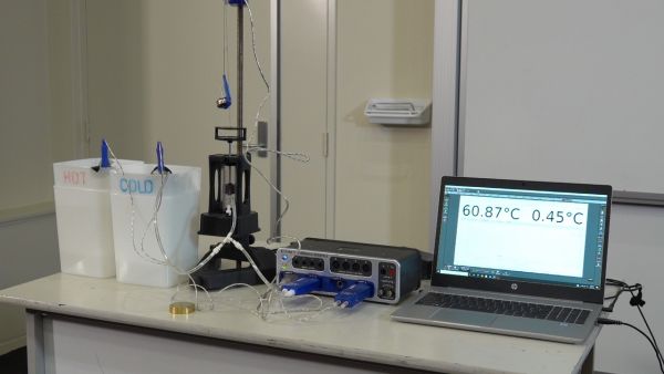
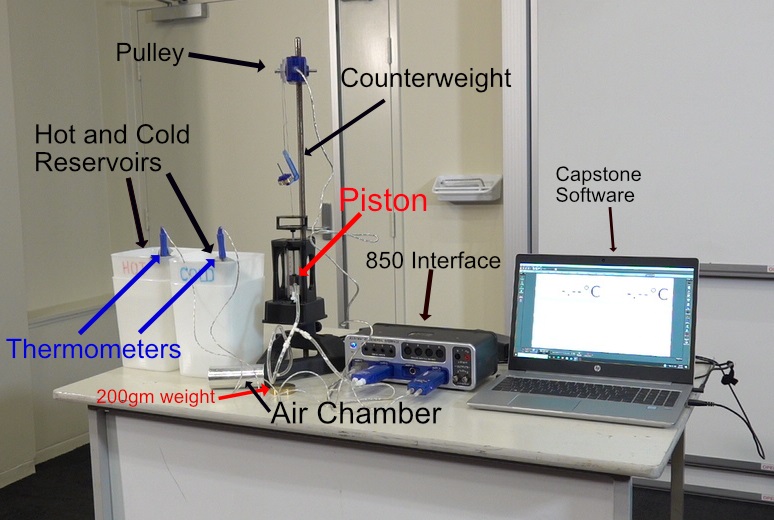
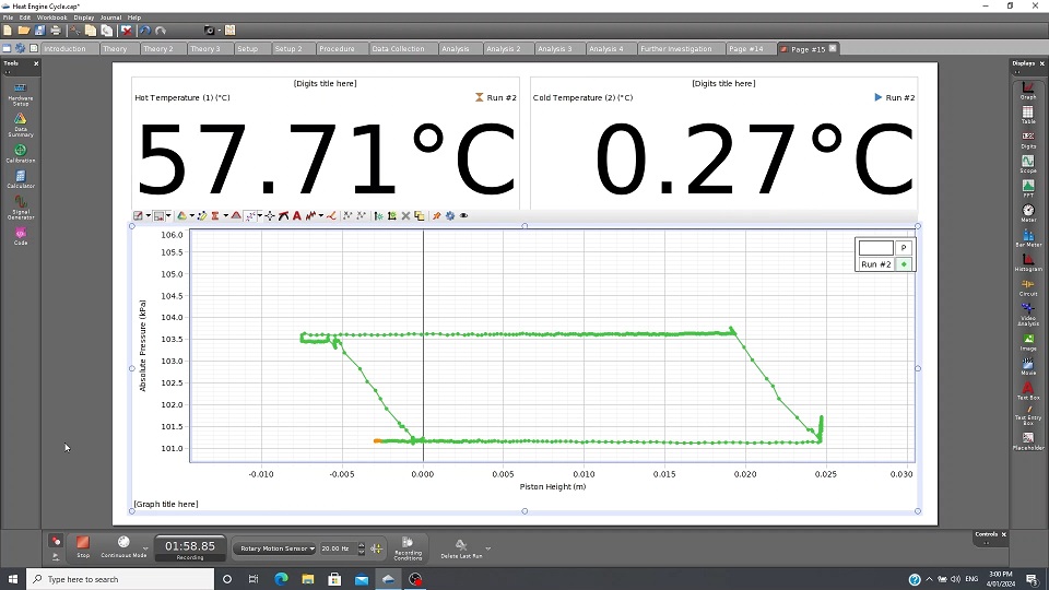
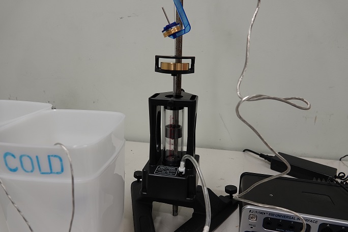
Heat Engine Cycle Apparatus and Graph
DESCRIPTION
Initially the piston is placed about 2-3cm above the bottom of the cylinder. 48.5gm hangar weight is connected to top of the piston and is placed over PASPORT Rotary Motion via a thread. An Air Chamber is connected to the piston and PASPORT Dual Pressure Sensor via T junction and tubing. The thermometers are placed in the Hot and Cold Water Reservoirs respectable. The Air Chamber is placed in the Cold Water Reservoir. The piston will lower and come to rest. The Capstone software is ready to take readings. The 200gm weight is placed on top of the piston. The piston will lower about 0.5cm and pressure reading will increase, as shown by the Capstone Graph Program. This process an Adiabatic process due to no change in temperature of the gas in the Air Chamber and Piston. The Air Chamber is now transferred to the Hot Water Reservoir. The Piston will move upwards while the Pressure reading will remain constant. This an Isobaric process. Work has been done on the Piston from the thermal energy extracted the Hot Water Reservoir. The piston is allowed to come to rest. The 200gm weight is now removed. The piston rises 0.5cm and the pressure drops. This also an Adiabatic process since the temperature of the air/gas has changed. The Air Chamber is now placed in the Cold Water Reservoir. The piston will lower and return to its original position. The Piston has done work by exhausting thermal energy to the Cold Water Reservoir. The resulting graph from the Capstone resembles the Carnot Cycle of a Heat Engine.
During the 1st process of the cycle when the weight was added the piston the internal energy ΔU=nCVΔT didn’t change since the temperature was kept constant.
According to the First Law of Thermodynamics ΔU=Q-W
where W is the work done by the gas
Q is the heat added to the gas.
In this case W=Q where Q is the heat exhaust to the Cold Water Reservoir.
W is the work done by gas when the weight was placed on top of the Piston.
During the 2nd process of the cycle when the Air Chamber was submerged in the Hot Water Reservoir. Heat was added to the gas Qp=nCPΔT
Where n is the number of moles of gas in the Air Chamber, and CP is the molar heat capacity of the gas for constant pressure. The work done by the gas is W=Q-ΔU. Q is the energy added to gas when the Air Chamber was submerged in the Hot Water Reservoir and ΔU=nCvΔT, where Cv is the molar heat capacity for constant volume.
Since air consists mostly of diatomic molecules, Cv= 5/2xR, and Cp= 7/2xR.
During the 3rd process of the cycle when the weight is lifted off the piston while the gas is held at a hotter temperature. Heat is added to gas and the gas expands doing work, during this isothermal process.
The work done is given W=nRTln(Vf/Vi)
Where Vi is the initial volume at the beginning of the isothermal process and Vf is the final volume at the end of the isothermal process. Since the change in internal energy is zero for an isothermal process, the First Law of Thermodynamics shows that the heat added to to the gas equal to the work done by the gas.
ΔU=Q-W=0
In the final part of the cycle, heat is exhausted from the gas to the cold reservoir, returning the piston to its original position. The process is isobaric and the same equation apply as in the second part of the cycle.
Qp=nCPΔT