Eh-3 The Hall Effect in P and N Type Germanium
Aim
To demonstrate that when a magnetic field is applied transverse to the current in a (semi)conductor a potential difference is developed along a direction perpendicular to both the current and the magnetic field.
Apparatus
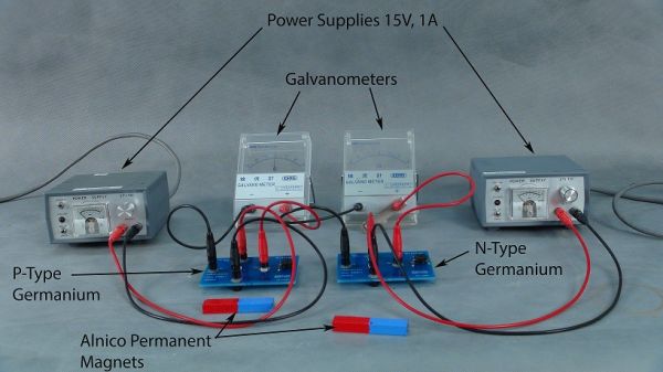
- P and N type germanium wafers
- 6 volt battery
- Bar magnet
- Galvamp / demonstration galvanometer
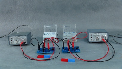
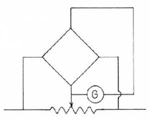
Hall Effect Setup and Circuit.
Description
The galvanometer is connected to the Hall voltage sockets (VH) of one of the germanium wafer units. The P and N type units are connected in series (blue current sockets) with the battery and the small trim potentiometer incorporated with the slice is adjusted to zero the galvanometer.
The north pole of the bar magnet is slowly brought over but not touching the slice. The sensitivity of the galvanometer is adjusted for best effect and the deflection direction noted. Switching over to the second wafer an opposite direction of deflection is observed demonstrating that in N and P type Ge the carriers are of opposite charge.