Ed-3 LC Resonance
Aim
To demonstrate the resonance frequency of a LC Circuit.
Apparatus
- LC Circuit
- Signal Generator
- MDO34 Mixed Domain Oscilloscope.
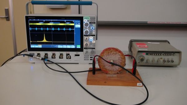
LC Resonance Setup.
Description
The resonance frequency can be calculated be the formula.

Where L is inductance
C is capacitance
In our circuit we have an inductance of 14mH and a capacitance of 0.001μF, giving a resonance frequency of approx. 40KHz.
A signal generator is connected to the LC circuit, with the oscilloscope connected to connected to the signal generator output and across the capacitor on two channels. Applying a sine wave to the LC circuit, the resonance frequency can be found be adjusting the frequency until the signal across the capacitor reaches a maximum Vp-p value.
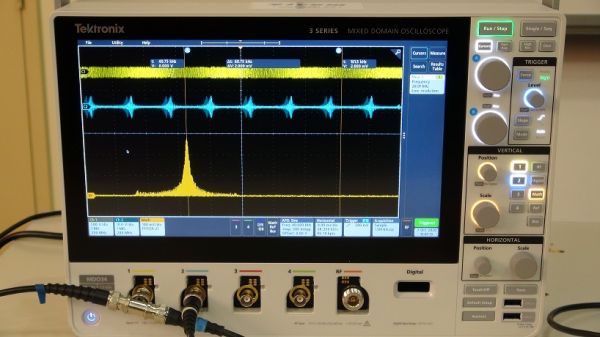
To obtain an Amplitude vs Frequency response of the circuit the MDO34 Mixed Domain Oscilloscope can be utilised. The Arbitrary Function Generator utility of the MDO34 can be used to generate a Sweep waveform to sweep across the resonance frequency in quick time. A Sweep waveform from 20KHz to 60KHz with a frequency of 100Hz is best suited to probe the circuit. The Sweep waveform and output across the capacitor can be both viewed on the screen. The resonance frequency can be observed across the capacitor. Using the Math Function on the Scope, a Fast Fourier Transform FFT can be performed on the channel that is connected to the capacitor output. This will produce an Amplitude vs Frequency trace. The resonance frequency can be determined by positioning the cursor on the peak value, on the classic bell shape response of the circuit.